 Read More

 Get A Quote

How Electromagnetic Flow Meters Deliver Accurate Readings in Raw Sewage and Sludge Lines
Home / News / Industry News / How Electromagnetic Flow Meters Deliver Accurate Readings in Raw Sewage and Sludge Lines
Product Category
NEW Category
Contact us
Contact Us
We specialise in the research, development and manufacture of electrical wires and cables.
 +86 13967196545
Related News
- How Integrated Electromagnetic Flow Meters Optimize Municipal Water Treatment Performance
- Electromagnetic Flow Meter vs. Vortex Flow Meter: Principles, Differences, and Selection Guide
- Pangu Electromagnetic Flowmeters Cover Six Critical Industries, Enabling Process Control and Energy Savings
- Solving Flow Measurement Failures: High-Precision Electromagnetic Flowmeter for Harsh Industrial Applications
How Electromagnetic Flow Meters Deliver Accurate Readings in Raw Sewage and Sludge Lines
Content
- 1 How Electromagnetic Flow Meters Measure Flow Inside a Wastewater Line
- 2 Why Treatment Plants Move Away from Mechanical and Differential Meters
- 3 Comparing Measurement Accuracy Across Technologies
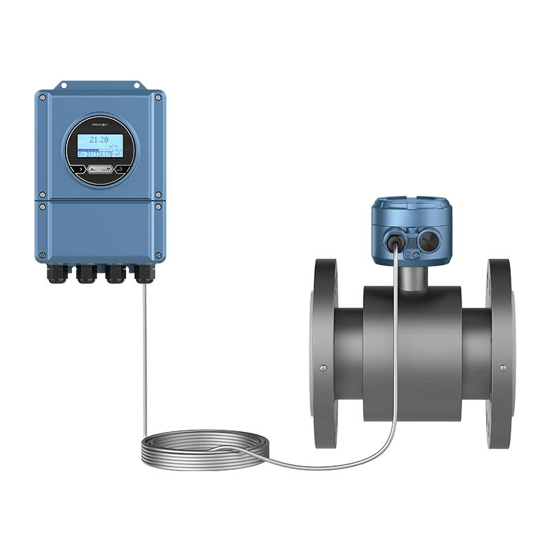
- 4 Core Components of a Slurry Type Electromagnetic Flowmeter
- 5 Signal Stability Across a Full Operating Shift
- 6 Sizing and Selecting a Meter for Wastewater Duty
- 7 Five Year Maintenance Cost Comparison
- 8 Installation Practices That Protect Long Term Accuracy
- 9 Weighing the Full Picture: A Multi-Criteria View
- 10 Meeting Regulatory and Billing Grade Requirements
- 11 Planning for Total Lifecycle, Not Just Purchase Price
- 12 Where Wastewater Flow Monitoring Is Heading
- 13 Common Field Problems and How to Read Them
- 14 Frequently Asked Questions
- 14.0.1 Q1: Can an electromagnetic flow meter measure flow in a partially full pipe?
- 14.0.2 Q2: How often does a sensor used on raw sewage need recalibration?
- 14.0.3 Q3: Does grease buildup on the liner affect accuracy?
- 14.0.4 Q4: What minimum conductivity does wastewater need for reliable measurement?
- 14.0.5 Q5: Is a slurry rated meter necessary for every sludge application?
How Electromagnetic Flow Meters Measure Flow Inside a Wastewater Line
A treatment plant operator rarely sees the liquid moving through a buried pipe, yet every dosing pump, aeration blower, and billing report downstream depends on knowing exactly how much of it passed by. This is the quiet job of a sewage electromagnetic flow meter: converting an invisible, often abrasive, often opaque stream into a stable electrical signal that a control room can trust.
The working principle has nothing to do with moving parts. Two coils mounted outside the pipe generate a magnetic field across the flow path. As the conductive liquid, in this case wastewater carrying dissolved salts, moves through that field, it generates a small voltage between two electrodes placed on the pipe wall. The faster the liquid moves, the larger that voltage becomes. A transmitter reads the voltage, applies a calibration factor tied to the pipe diameter, and outputs a flow rate value in real time.
Because the measurement depends on liquid conductivity rather than clarity or particle content, this technology tolerates conditions that would foul or damage mechanical meters within weeks. Raw influent loaded with grit, fibrous solids, and grease is a routine day for this sensor category, not an exception that requires special handling.
Field note: Municipal plants report that once an electromagnetic sensor is correctly grounded and the pipe stays full, drift over a full year typically stays within a fraction of a percent, without any moving element to wear down.
Why Treatment Plants Move Away from Mechanical and Differential Meters
Three flow measurement families dominate older wastewater infrastructure: mechanical meters with spinning turbines or paddlewheels, differential pressure meters that infer flow from a pressure drop across a restriction, and electromagnetic meters with no obstruction in the flow path at all. Each behaves differently once solids, fibers, and biofilm enter the picture.
| Attribute | Mechanical Meter | Differential Pressure Meter | Electromagnetic Meter |
|---|---|---|---|
| Moving parts in the flow path | Yes | No, but restriction present | None |
| Pressure loss introduced | Moderate to high | High | Negligible |
| Tolerance to fibrous solids | Poor, jams over time | Poor, restriction clogs | Good |
| Typical recalibration interval | 6 to 12 months | 6 to 12 months | 24 to 36 months |
| Turndown ratio | Narrow | Narrow | Wide |
The absence of an obstruction matters more than it first appears. A restriction plate or a spinning rotor is exactly where rags, wipes, and grit accumulate in raw sewage. Once that buildup begins, the reading degrades gradually and silently, which is far more dangerous operationally than an obvious failure because dosing and billing decisions keep relying on a number that has quietly drifted off.
Comparing Measurement Accuracy Across Technologies
Accuracy claims on a datasheet only mean something when tested under realistic solids loading rather than clean water. The chart below reflects typical field-accuracy ranges reported by plant instrumentation teams after twelve months of continuous raw influent service, expressed as percentage of reading.
The gap widens further once solids content rises above typical primary influent levels, since mechanical and differential technologies rely on a clean flow profile that heavy fiber loading distorts.
Core Components of a Slurry Type Electromagnetic Flowmeter
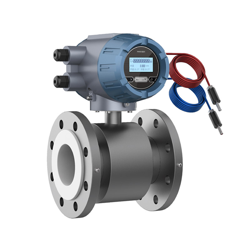
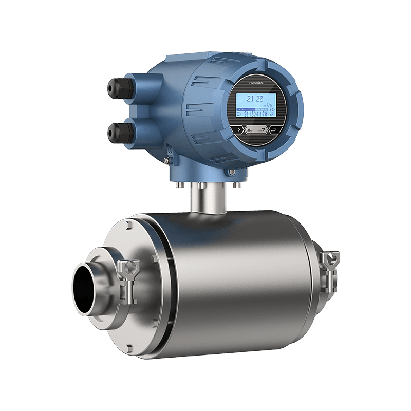
Understanding the parts helps an engineer specify the right variant for a lift station, an aeration basin feed line, or a sludge transfer line. A slurry type electromagnetic flowmeter is built specifically to handle the heavier solids fraction found in primary sludge, thickened sludge, and dewatering feed lines, where standard liners and electrode materials wear faster.
- Excitation coils that generate the alternating magnetic field across the pipe cross section
- A liner, commonly rubber, polyurethane, or PTFE, chosen to resist abrasion from grit and chemical attack from digester or dosing chemicals
- Signal electrodes in contact with the liquid, available in stainless steel, hastelloy, or tantalum depending on corrosivity
- A converter or transmitter housing that processes the raw signal and outputs 4 to 20 mA, pulse, or digital communication
- Grounding rings or grounding electrodes that stabilize the reference potential, critical in plastic or lined pipe sections
Liner selection deserves particular attention in sludge service. Polyurethane liners handle abrasive grit better than standard rubber, while PTFE liners resist the ferric chloride or polymer conditioning chemicals commonly dosed ahead of dewatering equipment. Choosing the wrong liner for the chemical environment is one of the most common causes of premature failure reported by maintenance teams.
Signal Stability Across a Full Operating Shift
One advantage rarely captured on a spec sheet is how flat the output signal stays during flow surges, such as a storm event pushing combined sewer flow through a lift station. The line chart below traces a representative eight-hour shift, comparing raw flow demand against the metered signal.
The two traces stay close together through the peak surge rather than diverging, because the sensor has no mechanical inertia and no restriction that reacts slowly to a sudden increase in velocity. That responsiveness is exactly what a pump station control loop needs to avoid overflow events during storm loading.
Sizing and Selecting a Meter for Wastewater Duty
Correct sizing starts with velocity, not pipe diameter alone. A meter body sized for full-scale accuracy at low velocity often loses resolution at the low flows typical of overnight periods, while an undersized body creates unnecessary headloss during peak flow. Most treatment applications target a normal operating velocity in the middle of the sensor range rather than at either extreme.
| Application | Typical Line Size | Recommended Liner | Electrode Material |
|---|---|---|---|
| Raw influent metering | Medium to large | Rubber or polyurethane | Stainless steel |
| Primary or secondary sludge | Small to medium | Polyurethane | Stainless steel or hastelloy |
| Chemical dosing lines | Small | PTFE | Tantalum or hastelloy |
| Effluent discharge metering | Medium to large | Rubber | Stainless steel |
For industrial wastewater measurement outside municipal settings, such as food processing rinse water or textile dye effluent, conductivity can swing widely between batches. Confirming a minimum conductivity threshold with the manufacturer before ordering avoids a mismatch that only becomes obvious once the unit is installed and reading erratically.
Installation Practices That Protect Long Term Accuracy
Sensor selection only delivers on its accuracy promise when installation follows a few disciplined rules. These are the practices that separate a meter reading within its rated tolerance for a decade from one that needs recalibration within the first year.
- Keep the pipe full at all times at the sensor location, which usually means avoiding installation immediately downstream of an open channel or a partially filled gravity line
- Maintain adequate straight pipe upstream and downstream of the sensor to let the velocity profile settle before it reaches the electrodes
- Ground the meter body independently of relying on pipe flanges alone, especially in plastic, lined, or cathodically protected pipe sections
- Avoid installing directly downstream of control valves, pumps, or elbows that introduce swirl into the flow profile
- Verify orientation so electrodes sit on a horizontal axis in horizontal runs, reducing the chance of air pockets interfering with the measurement
Grounding failures are the single most common root cause behind noisy or unstable readings reported during commissioning. A five-minute continuity check during startup avoids weeks of troubleshooting an intermittent signal later.
Weighing the Full Picture: A Multi-Criteria View
No single number captures the tradeoffs between technologies. The radar comparison below scores electromagnetic and mechanical meters across five operational criteria on a relative scale, where a larger enclosed area represents stronger overall performance.
The gap is widest in headloss and long-term accuracy, exactly the two criteria that drive both energy costs and the reliability of downstream billing or regulatory reporting figures.
Meeting Regulatory and Billing Grade Requirements
Many jurisdictions require flow data used for discharge permits or interagency billing to meet a documented accuracy standard, and the meter alone rarely satisfies that requirement without a supporting verification program. Regulators typically expect three things: a traceable calibration record, a documented installation that matches manufacturer guidance on straight pipe runs, and a periodic verification schedule that confirms the sensor still performs within its stated tolerance band.
Plants that treat calibration as a one-time commissioning event rather than an ongoing program tend to discover accuracy gaps only when a regulator audits the record or when a billing dispute forces a closer look at historical data. Building a simple verification log, even something as basic as an annual spot check against a portable reference meter, closes that gap at minimal cost.
Documentation also matters for insurance and asset management purposes. A sensor with a clear installation record, including photographs of the grounding connections and straight pipe layout, resolves warranty claims far faster than a bare serial number on a maintenance spreadsheet.
Planning for Total Lifecycle, Not Just Purchase Price
Procurement decisions driven purely by the lowest quoted price often overlook three cost categories that dominate total lifecycle spending: energy consumption tied to headloss, labor hours spent on unplanned service calls, and the operational risk of a misreported flow figure feeding a regulatory report. A sensor with a slightly higher purchase price but negligible headloss and a multi-year recalibration interval frequently wins on total cost within the first two to three years of service.
Energy cost deserves particular attention on large diameter influent lines, since even a small pressure loss compounds into meaningful pump energy over continuous operation. Because an electromagnetic sensor introduces no obstruction into the flow path, it avoids this recurring cost entirely, unlike differential pressure designs that rely on a restriction to generate their signal.
Spare parts strategy is another lifecycle factor worth planning early. Because the converter electronics and the sensor body are often modular, many plants stock a single spare converter that can serve multiple sensor bodies across the facility, reducing the working capital tied up in spare inventory compared with mechanical designs that require model-specific wear parts.
Where Wastewater Flow Monitoring Is Heading
Instrumentation teams are increasingly pairing flow data with other process signals, such as conductivity or level, on a shared communication network rather than wiring each sensor back to the control room independently. This shift reduces cabling costs on retrofit projects and simplifies diagnostics, since a technician can pull historical trend data for several parameters from one interface instead of walking the plant with a handheld meter.
Remote diagnostics are also becoming standard on newer transmitters, allowing a technician to review coil resistance, grounding quality, and signal noise from a central workstation before dispatching a field crew. For plants managing dozens of metering points across a collection system, that capability shortens the time between a symptom appearing and a root cause being identified, which directly reduces the risk of an undetected billing or compliance discrepancy.
None of these developments change the underlying physics of the measurement, but they do lower the operational burden of keeping a fleet of sensors within tolerance across a large service area, which is often the deciding factor when a utility standardizes on one flow measurement technology plant-wide.
Common Field Problems and How to Read Them
Even a well specified sensor can produce misleading readings if a handful of known failure modes go unrecognized. Field technicians can usually diagnose the cause quickly once the symptom is matched to its likely origin.
| Symptom | Likely Cause | Typical Fix |
|---|---|---|
| Reading drops to zero intermittently | Pipe running partially full | Relocate sensor to a location guaranteed full, or add a downstream weir |
| Noisy or jumping signal | Poor grounding | Install or verify grounding rings and bonding straps |
| Steady but incorrect offset | Liner buildup or coating from grease | Schedule liner inspection and cleaning |
| Gradual accuracy drift over years | Electrode coating from scale | Chemical or mechanical electrode cleaning during service interval |
Most of these symptoms are preventable with the installation discipline covered earlier, which is why commissioning checklists consistently outperform reactive troubleshooting in total cost of ownership.
A useful habit for maintenance teams is trending the raw signal noise level alongside the flow reading itself, rather than only logging the flow value. A steady rise in background noise over several weeks, even while the flow reading still looks reasonable, often precedes a visible fault by enough time to schedule a planned inspection instead of reacting to an unplanned alarm. This kind of early warning trend is one of the more underused diagnostic tools available on modern transmitters, largely because it requires pulling a secondary data channel that many control systems do not display by default.
Cross-checking two independent meters at a junction, where the flow arriving from separate lines should sum to match a downstream total, is another practical verification method that does not require taking any sensor out of service. Persistent mismatches beyond the expected measurement tolerance point toward one meter needing attention well before it drifts far enough to trigger an alarm on its own.
Frequently Asked Questions
Q1: Can an electromagnetic flow meter measure flow in a partially full pipe?
Standard closed-pipe electromagnetic meters require the pipe to run full at the sensor location, since the magnetic field measurement assumes liquid fills the entire cross section. Open channel or partially full applications require a different sensor category built specifically for that condition.
Q2: How often does a sensor used on raw sewage need recalibration?
Many plants extend recalibration intervals to two or three years for electromagnetic sensors on raw influent, compared with annual or semiannual checks common for mechanical meters, though local regulatory requirements for billing meters may still mandate a fixed schedule regardless of technology.
Q3: Does grease buildup on the liner affect accuracy?
A thin, uniform coating generally has limited impact, but uneven buildup that narrows the effective bore or covers one electrode more than the other can introduce a measurable offset, which is why periodic liner inspection remains part of a standard maintenance plan.
Q4: What minimum conductivity does wastewater need for reliable measurement?
Municipal wastewater almost always exceeds the minimum conductivity threshold required by these sensors, since dissolved salts from domestic and industrial sources keep conductivity well above typical minimum specifications, though unusual process streams should always be checked against the specific model requirement.
Q5: Is a slurry rated meter necessary for every sludge application?
Thin, low-solids streams such as return activated sludge may perform adequately with a standard liner and electrode configuration, but higher solids content lines such as thickened or dewatered sludge feed benefit from the reinforced liner and electrode materials built into slurry rated designs.
PREV:How Integrated Electromagnetic Flow Meters Optimize Municipal Water Treatment Performance
NEXT:How to Choose a Flow Meter That Survives Aggressive Chemical Service
NEXT:How to Choose a Flow Meter That Survives Aggressive Chemical Service
Interested in cooperation or have questions?
Contact Us Now!
Kelly

+86 13967196545

pangusales@vip.163.com
Production Base:

Building 1 and Building 42, No. 889 Huancheng North Road, Deqing County, Huzhou City, Zhejiang Province
Jiji
+86 15397010616
pgsalesjiji@vip.163.com

+86-0571-87770830
Corporate Headquarters:
602-702, Block D, Building 3, Area B,Xigang New Territories, 206 Zhenhua Road,Hangzhou City, Zhejiang Province, China

Copyright © Hangzhou Pangu Automation System Co., Ltd. Rights Reserved.
Custom Digital Panel Mount Industrial Instruments Suppliers
