 Read More

 Get A Quote

Flow Measurement Challenges in Industry: Real Causes and Practical Fixes
Home / News / Industry News / Flow Measurement Challenges in Industry: Real Causes and Practical Fixes
Product Category
NEW Category
Contact us
Contact Us
We specialise in the research, development and manufacture of electrical wires and cables.
 +86 13967196545
Related News
- Why Does an Electromagnetic Flow Meter Show Flow in an Empty Pipe? (Causes & Troubleshooting)
- The Critical Role of Flow Measurement in Modern Industrial Operations
- Pangu Electromagnetic Flowmeters Cover Six Critical Industries, Enabling Process Control and Energy Savings
- Potable Water Flow Meter: Accurate Measurement for Utilities & Industry
Flow Measurement Challenges in Industry: Real Causes and Practical Fixes
Content
- 1 The Five Complaints That Reach the Instrument Engineer
- 2 Fluid Condition Challenges: Conductivity, Solids and Entrained Gas
- 3 Installation and Hydraulic Challenges
- 4 Calibration and Traceability Challenges
- 5 Matching the Measurement Path to the Duty
- 6 Heat, Steam and Energy Metering Challenges
- 7 Data Recording and Reconciliation Challenges
- 8 A Practical Checklist Before You Specify or Replace a Meter
- 9 Frequently Asked Questions
Two plants run the same DN80 electromagnetic flow meter on the same duty. One holds within 1% of the reference across the full range. The other swings 6% every time a reciprocating pump starts, and the monthly reconciliation turns into a two-day argument.
The difference is rarely the instrument. Flow measurement challenges in industry come from four places, in this order of likelihood: installation hydraulics, fluid behaviour, calibration and traceability, and only then the meter itself. Fix the first three and most sensors behave. Ignore them and no datasheet will rescue the reading.
Here is what those challenges look like on site, how to tell them apart, and which measurement path suits which duty.
The Five Complaints That Reach the Instrument Engineer
Across water, chemical, HVAC and slurry duties, the same five problems come back.
- Drift and instability. The reading moves when the process does not, or zero wanders after maintenance.
- Low-flow and empty-pipe errors. Minimum night flows read high, or the output drops out entirely.
- Coating and fouling. Accuracy fades over weeks as electrodes and liners collect deposits.
- Process change. A new formulation or a hotter stream invalidates the original assumptions.
- Numbers that will not reconcile. Two meters on one line disagree by more than their combined uncertainty allows.
Each points to a different root cause. Treating all five as a faulty meter is the fastest way to waste a replacement budget.
Fluid Condition Challenges: Conductivity, Solids and Entrained Gas
Fluid behaviour causes more measurement error than any electronics failure.
Conductivity sets the floor
Electromagnetic meters need a conductive liquid, typically above 5 µS/cm. In deionised water, some solvents and certain condensates the signal-to-noise ratio collapses, so readings turn erratic rather than simply offset. Low-conductivity designs raise excitation and use different preamplifier stages to keep the signal usable.
Solids, fibres and abrasion
Slurries, pulp, dye wastewater and mineral tailings attack electrodes and liners in different ways. Hard particles abrade, chemical pulps coat, fibrous media wrap around electrodes. A meter chosen for clean reagents will fail in a lime slurry line within months, which is why chemical industry flow measurement duties need electrode and liner selection driven by particle size, sharpness and chemistry rather than flow rate alone.
Entrained gas and two-phase flow
Air pockets, gas breaking out of solution and pump cavitation all distort the reading. The signature is spikes that track pump cycling, or a reading that falls when flow actually rises.
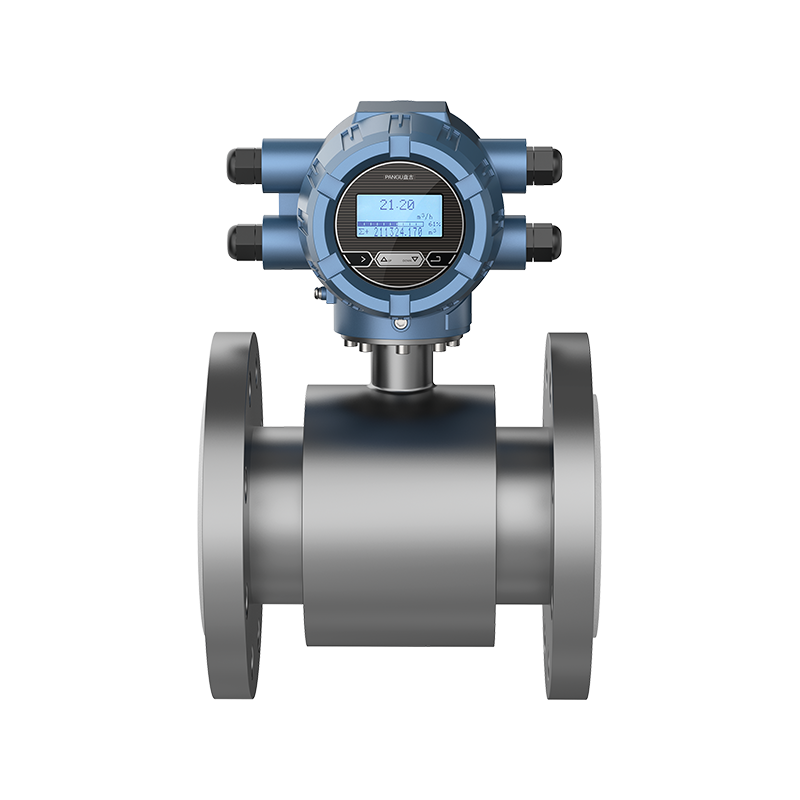
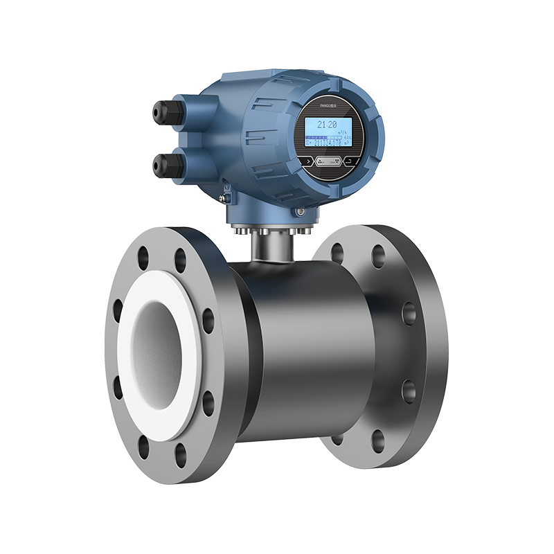
 Low Conductivity Electromagnetic Flowmeter PMF-DIt solves flow-display fluctuations from noise in low-conductivity fluids (>5 μS/cm), with 25 Hz excitation and filtering algorithms.View Product →
Installation and Hydraulic Challenges
Most "inaccurate meter" cases are piping cases. The instrument is doing exactly what the flow profile tells it to do.
- Missing straight run. A control valve, elbow or reducer close upstream creates swirl and an asymmetric profile. Five to ten diameters upstream and three to five downstream is a workable starting point.
- Grounding. Electromagnetic meters depend on a stable reference. Unbonded flanges, lined pipe and long cable runs introduce noise that looks like flow.
- Partially filled pipe. Gravity drains and open discharge lines break the full-pipe assumption and cause over-reading.
- Sensor orientation. In horizontal pipe, electrodes belong at 3 and 9 o'clock so air and sediment stay off the measuring surface.
- Electrical noise. Variable-frequency drives and shared cable trays are common sources of jumpy signals.
Rule of thumb: if a reading changes with pump cycling, valve position or time of day, suspect hydraulics and grounding before ordering a new meter.
Calibration and Traceability Challenges
An accuracy figure is only as good as the rig behind it. Water-flow calibration normally uses one of two methods: the standard meter method, which compares the unit under test with a master meter, or the static gravimetric method, which weighs the water collected over a timed interval and is independent of any reference instrument.
Coverage matters at both ends of the size range. A line that can verify DN15 to DN1000 on three independent water circuits handles a small dosing meter and a transmission main on the same day.
DN15 – DN1000Calibrated water flow range on a single rig
3Independently operated calibration circuits
2Methods: standard meter and static gravimetric
Traceability is the second half of the problem. National metrology licensing, an ISO10012 measurement management system and product approvals such as CE electromagnetic compatibility and explosion-proof certification are what allow a reading to be used for billing or safety interlocks instead of trend-only monitoring.
Matching the Measurement Path to the Duty
The useful question is not which flow meter is best, but which principle tolerates this fluid, this pipe and this process window.
| Duty | Main challenge | Practical approach |
|---|---|---|
| Potable and process water | Low night flow, air entrainment | Full-bore electromagnetic meter with empty-pipe detection |
| Raw sewage and sludge | Ragging, fouling, abrasion | Electromagnetic meter with abrasion-resistant liner and scheduled cleaning |
| Mineral slurry and tailings | Electrode wear, surface coating | Slurry-type electromagnetic meter sized for velocity, not pipe size |
| Low-conductivity liquid | Weak signal, electrical noise | Low-conductivity electromagnetic design with boosted excitation |
| Steam and hot water for billing | Density change, wet steam | Flow computer with pressure and temperature compensation |
| Chilled and hot water in buildings | Wide turndown, low velocity | Electromagnetic heat meter with paired temperature sensors |
| Aggressive chemicals | Corrosion, material attack | Lined electromagnetic meter matched to the chemical |
Notice how often the answer is an electromagnetic meter, and how much the detail changes: liner, electrode, sizing velocity, grounding and compensation. Slurry duty is the clearest case. An undersized meter runs too fast and wears out; an oversized one runs too slow to measure.
 Slurry Type Electromagnetic Flowmeter PMF-SMeasures slurry with up to 30% solids, featuring 25 Hz excitation, improved signal processing, and filtering for stable readings in industrial control.View Product →
Heat, Steam and Energy Metering Challenges
Energy measurement adds variables to a reading that was already difficult. Steam is compressible, so volumetric flow means little without pressure and temperature; the same mass of steam occupies very different volumes at 4 bar and at 10 bar. Heat metering needs a matched pair of temperature sensors, correct insertion depth and a calculation that follows an agreed standard.
Where money changes hands, the arithmetic has to be traceable. Fiscal flow computers handle density, enthalpy and compensation internally and keep a record of every correction applied. Building-level heating and cooling faces the same problem in smaller form, which is why HVAC heat metering depends as much on sensor pairing as on the flow element.
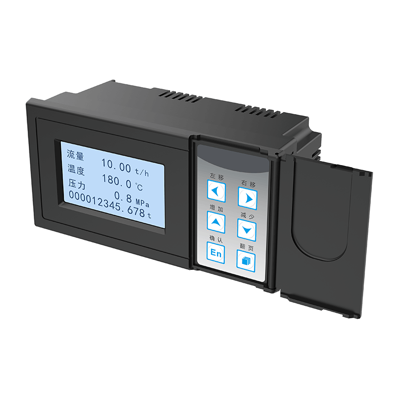 FX1100 Fiscal Flow Computer for Steam Gas HeatTotalizes steam, gas, and heat energy with trade settlement features, data logging, and communication protocols for traceable fiscal measurement.View Product →
Data Recording and Reconciliation Challenges
Many flow disputes are not measurement disputes at all; they are record-keeping disputes. A value sampled once an hour will miss the pump cycling that dominates a daily total, and a lost alarm log turns a solvable problem into an argument.
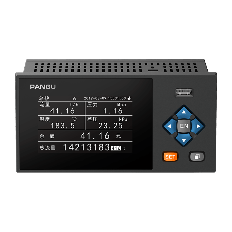
Multi-channel paperless recorders covering 4 to 48 channels let a plant log flow alongside temperature, pressure and status signals on one time base, so a discrepancy can be traced to a specific event instead of debated after the fact.
A Practical Checklist Before You Specify or Replace a Meter
- Confirm the real fluid: conductivity, solids content, fibre, gas fraction and temperature range.
- Measure the true flow window, including minimum night flow rather than design maximum only.
- Walk the pipe: upstream fittings, straight runs, full-pipe conditions and valve positions.
- Check grounding, cable routing and nearby drives before blaming the electronics.
- Decide what the reading is for: trending, control, internal allocation or billing.
- Match the verification plan to that purpose and confirm the calibration range covers the working range.
- Plan cleaning, zero checks and periodic verification from day one.
Frequently Asked Questions
Q1: What is the most common cause of flow measurement error in industry?
Installation. Insufficient straight run, poor grounding and partially filled pipe account for more field errors than instrument faults, and none of them appear on a calibration certificate.
Q2: Can electromagnetic flow meters handle slurries?
Yes, with the right build. Abrasion-resistant liners and correctly matched electrodes handle mineral slurries and sludge, provided the meter is sized so velocity stays inside a range that measures reliably and limits wear.
Q3: How often should an industrial flow meter be verified?
Annually is a common baseline for billing duty, with a zero check after any maintenance that disturbs the sensor or the pipe. Duties with abrasive or coating media need shorter intervals.
Q4: Why do two meters on the same pipe disagree?
Usually because they are not measuring under the same conditions: different straight runs, different grounding, or one sitting where air accumulates. Compare installation first, then calibration history.
Flow measurement challenges in industry are rarely solved by a better sensor alone. They are solved by matching the principle to the fluid, installing it where the hydraulics allow, proving it against a traceable reference, and recording the result well enough to defend it later. Do those four things and the number on the report stops being a debate.
PREV:Smart Electromagnetic Flow Meters Company: Reliable Calibrated Magnetic Flow Measurement Solutions
NEXT:Electromagnetic Flow Meter Applications Across Water, Chemical and Slurry Lines
NEXT:Electromagnetic Flow Meter Applications Across Water, Chemical and Slurry Lines
Interested in cooperation or have questions?
Contact Us Now!
Kelly

+86 13967196545

pangusales@vip.163.com
Production Base:

Building 1 and Building 42, No. 889 Huancheng North Road, Deqing County, Huzhou City, Zhejiang Province
Jiji
+86 15397010616
pgsalesjiji@vip.163.com

+86-0571-87770830
Corporate Headquarters:
602-702, Block D, Building 3, Area B,Xigang New Territories, 206 Zhenhua Road,Hangzhou City, Zhejiang Province, China

Copyright © Hangzhou Pangu Automation System Co., Ltd. Rights Reserved.
Custom Digital Panel Mount Industrial Instruments Suppliers
