 Read More

 Get A Quote

Electromagnetic Flow Meter Selection Guide: 5 Core Factors & On-Site Best Practices
Home / News / Industry News / Electromagnetic Flow Meter Selection Guide: 5 Core Factors & On-Site Best Practices
Product Category
NEW Category
Contact us
Contact Us
We specialise in the research, development and manufacture of electrical wires and cables.
 +86 13967196545
Related News
- Electromagnetic Flow Meters: Pros, Cons, Selection Guide, and FAQs
- Electromagnetic Flow Meter vs. Vortex Flow Meter: Principles, Differences, and Selection Guide
- 3 Inch Steam Flow Meter: Selection Guide, Accuracy Tips and Best Practices
- Electromagnetic vs Mechanical Flow Meters: How to Choose the Right One
Electromagnetic Flow Meter Selection Guide: 5 Core Factors & On-Site Best Practices
Content
In industrial automation, water treatment, and chemical processing, electromagnetic flow meters have become the gold standard for volumetric liquid flow measurement. Thanks to their unobstructed flow path, zero pressure drop, and high measurement accuracy, they handle everything from clean water to corrosive slurries.
However, improper selection often leads to premature equipment failure, inaccurate readings, and costly downtime. To help engineers and procurement specialists make the right choice, this comprehensive guide breaks down the 5 core selection factors and critical on-site installation best practices.

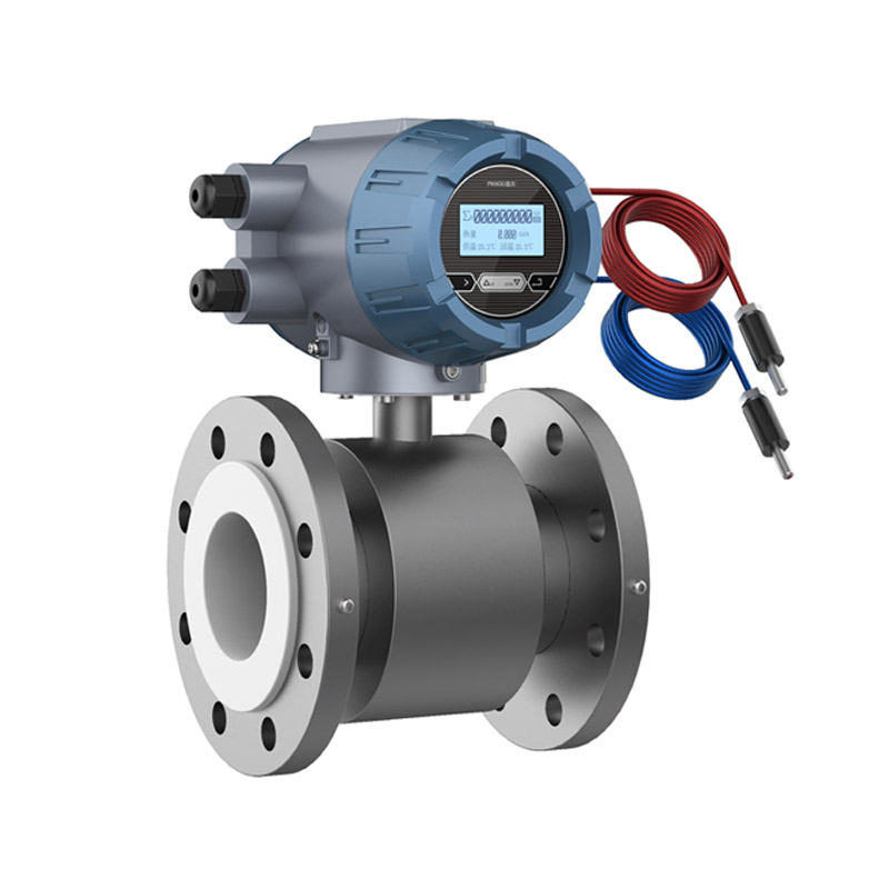
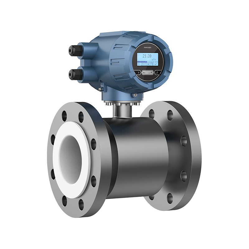
Figure 1: Electromagnetic Flow Meter Installation and Structural Layout
Part 1: The 5 Core Factors in Electromagnetic Flow Meter Selection
Before purchasing an electromagnetic flow meter, you must thoroughly evaluate your application’s process parameters. Here are the five key elements to consider:
1. Fluid Characteristics (Conductivity, Corrosiveness, and Solids)
- Conductivity Threshold: Electromagnetic flow meters operate on Faraday’s Law of Electromagnetic Induction, meaning the fluid must be conductive. The typical minimum conductivity requirement is >= 5 µS/cm (demineralized water, pure oils, and hydrocarbons cannot be measured).
- Liner Material Selection:
- PTFE / PFA: Excellent resistance to strong acids, alkalis, and high temperatures; ideal for harsh chemical applications.
- Polyurethane / Neoprene Rubber: Superior wear and abrasion resistance; best suited for abrasive media like wastewater, slurries, and mineral mud.
- Electrode Material Selection:
- 316L Stainless Steel: Standard for water, sewage, and mild chemicals.
- Hastelloy (C-276 / B): Recommended for chloride-bearing solutions and hydrochloric acid.
- Titanium (Ti) / Tantalum (Ta): Used for extreme, highly corrosive environments (e.g., strong oxidizers and hot acids).
2. Flow Velocity and Pipe Sizing
Do not blindly match the flow meter size to your existing pipe diameter. Proper sizing ensures optimal measurement stability.
- Optimal Economic Velocity: Aim for a fluid velocity between 1 m/s and 5 m/s.
- Low Velocity (< 0.5 m/s): Signals become too weak and prone to electromagnetic interference. In this case, reducers (smaller meter sizes) should be used to increase velocity.
- High Velocity (> 8 m/s): Causes rapid wear on liners and electrodes. Expanders (larger meter sizes) are recommended to lower the velocity.
3. Temperature and Pressure Ratings
- Pressure Rating: The meter's nominal pressure (PN rating) must exceed the maximum operating pressure of the pipeline (common industrial ratings include PN16, PN40, and PN100).
- Temperature Limits:
- Standard rubber liners generally max out around 80°C.
- PTFE/PFA liners can withstand operational temperatures up to 120°C to 180°C depending on the specific structural design.
4. Structural Design and Protection Class (Compact vs. Split Type)
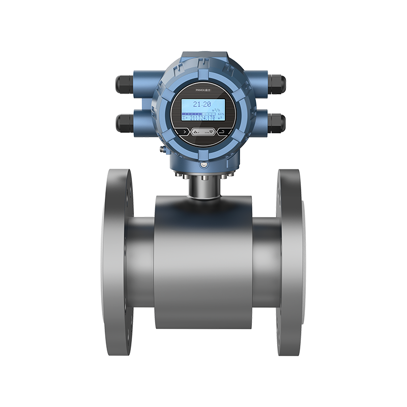
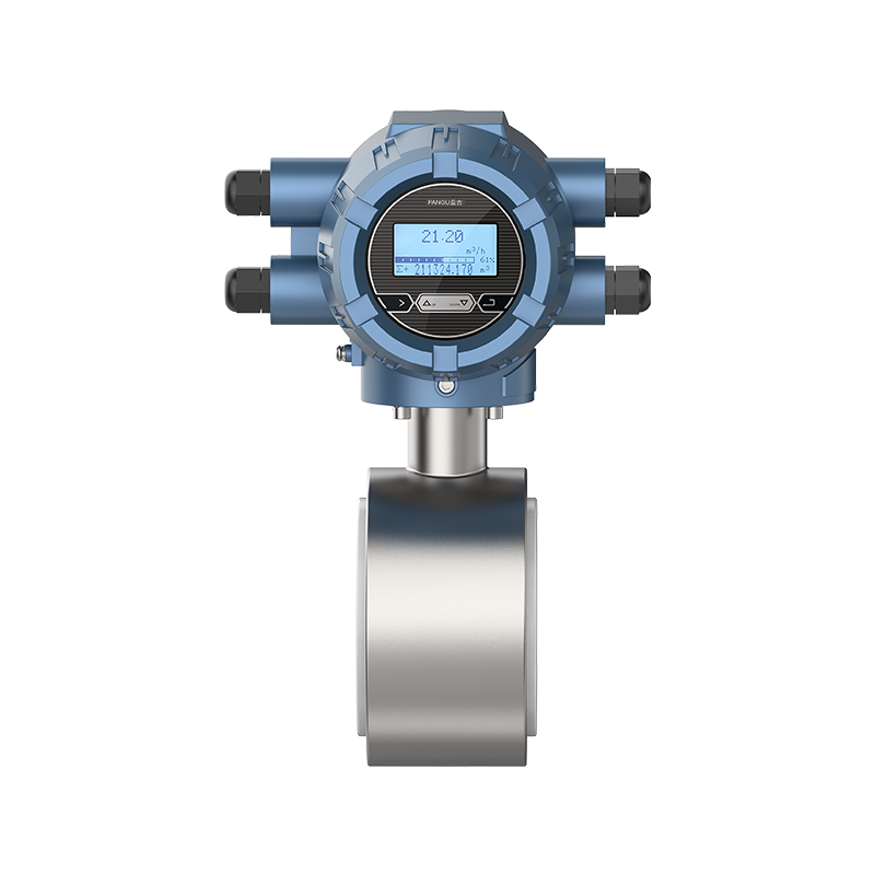
- Compact Type (IP65): The signal converter and sensor are integrated. Best for indoor, easily accessible, and well-ventilated environments.
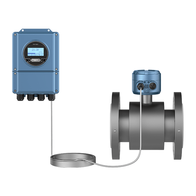
- Split Type (IP68): The sensor and converter are installed separately via a signal cable. This is mandatory for underground pits, submersed conditions, high humidity, severe vibration, or hard-to-reach elevated piping.
5. Output Signals and Industrial Communication Protocols
- Analog & Discrete Outputs: 4-20mA current loop, pulse/frequency output for basic control loops.
- Digital Fieldbuses: HART, Modbus RS485, or Profibus for seamless integration into modern PLC/DCS systems.
- Power Supply Options: Standard 220V AC or 24V DC, alongside battery-powered options for remote, off-grid field sites.
Part 2: On-Site Engineering Best Practices & Pitfall Avoidance
Even the most expensive flow meter will fail if installation guidelines are ignored. Keep these three rules in mind:
Strictly Follow Straight Pipe Requirements:
Install the meter with at least 5D (where D is the inner pipe diameter) of straight pipe upstream and 2D to 3D downstream. If valves, pumps, or elbows are located upstream, extend the upstream straight pipe to 10D or more to eliminate flow turbulence.
Never Skip Grounding:
The induced voltage in electromagnetic flow meters is in the millivolt range. When installing on plastic, fiberglass, or lined metal pipes, grounding rings or grounding electrodes must be used to neutralize stray electrical currents.
Ensure Full-Pipe Flow Conditions:
The measuring tube must remain completely full of liquid at all times. Avoid mounting the sensor at the highest point of a system or on a downward-discharging open pipe end where air pockets can form.
Part 3: Frequently Asked Questions (FAQ)
Can an electromagnetic flow meter measure air or gas?
No. Electromagnetic flow meters are strictly designed for conductive liquids. They cannot measure gases, vapors, or non-conductive liquids like pure oil.
What causes zero drift or unstable readings in electromagnetic flow meters?
Unstable readings are typically caused by insufficient straight pipe lengths, incomplete pipe filling, poor grounding, or heavy electrical interference from nearby variable frequency drives (VFDs) and motors.
Conclusion
Choosing the right electromagnetic flow meter is a critical balance between fluid chemistry, hydraulic parameters, and physical installation constraints. A well-engineered installation guarantees long-term measurement accuracy and heavily minimizes maintenance costs.
PREV:Insertion Electromagnetic Flowmeter Guide: Working Principle and Selection
NEXT:Magnetic Water Flow Meter Buyer's Guide: Types, Accuracy, and Applications
NEXT:Magnetic Water Flow Meter Buyer's Guide: Types, Accuracy, and Applications
Interested in cooperation or have questions?
Contact Us Now!
Kelly

+86 13967196545

pangusales@vip.163.com
Production Base:

Building 1 and Building 42, No. 889 Huancheng North Road, Deqing County, Huzhou City, Zhejiang Province
Jiji
+86 15397010616
pgsalesjiji@vip.163.com

+86-0571-87770830
Corporate Headquarters:
602-702, Block D, Building 3, Area B,Xigang New Territories, 206 Zhenhua Road,Hangzhou City, Zhejiang Province, China

Copyright © Hangzhou Pangu Automation System Co., Ltd. Rights Reserved.
Custom Digital Panel Mount Industrial Instruments Suppliers
