 Read More

 Get A Quote

Resolving Calibration Discrepancies: Weighing Method vs. On-Site Adjustment of Integral Electromagnetic Flow Meters
Home / News / Industry News / Resolving Calibration Discrepancies: Weighing Method vs. On-Site Adjustment of Integral Electromagnetic Flow Meters
Product Category
NEW Category
Contact us
Contact Us
We specialise in the research, development and manufacture of electrical wires and cables.
 +86 13967196545
Related News
- Electromagnetic vs Mechanical Flow Meters: How to Choose the Right One
- Electromagnetic Flow Meter Selection Guide: 5 Core Factors & On-Site Best Practices
- Electromagnetic Flow Meters: Pros, Cons, Selection Guide, and FAQs
- Electromagnetic Flow Meter vs. Vortex Flow Meter: Principles, Differences, and Selection Guide
Resolving Calibration Discrepancies: Weighing Method vs. On-Site Adjustment of Integral Electromagnetic Flow Meters
Content
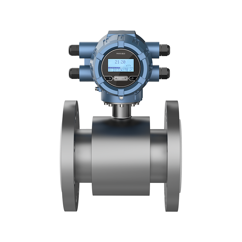
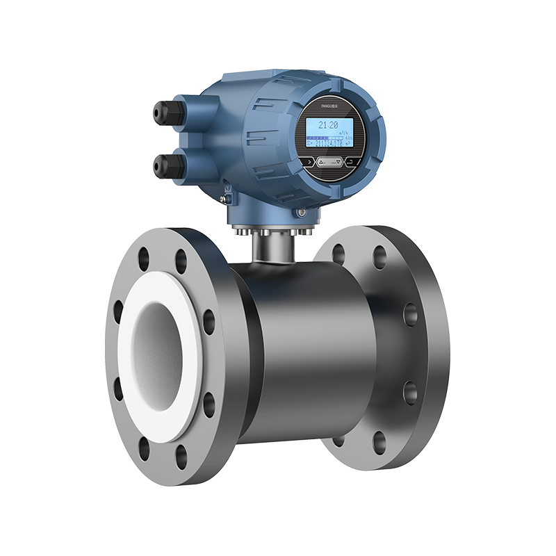
Picture this: You've just installed two brand-new integral electromagnetic flow meters on site. Everything looks solid, the piping is connected, and the commissioning checks are complete. But when you run a gravimetric calibration—using the weighing method—you notice a stubborn 2% discrepancy compared to the meter's readout.
Frustrating? Absolutely. Common? More than you might think.
Recently, a client reached out with this exact scenario involving their compact integral electromagnetic flowmeter units. After carefully recalculating the span factor and fine-tuning the zero point right there on the plant floor, they got both meters dialed in, passing the recalibration with flying colors. But why does this happen, and how can you handle it smoothly without tearing your hair out? Let's dive right in.
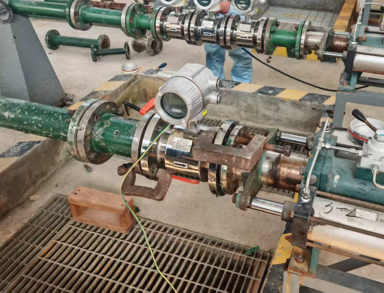
Why Does a Weighing Method Show a 2% Variance on an Integral Meter?
When field engineers compare a static or dynamic weighing system against a solid-state electromagnetic flowmeter, minor offsets are bound to pop up. It doesn't necessarily mean your flow meter is defective. Usually, the culprit lies in environmental or procedural variables:
- Fluid Density and Temperature Shifts: If the laboratory baseline temperature differs significantly from actual working conditions, fluid density changes can skew mass-to-volume conversions.
- Response Timing and Valve Lag: In gravimetric tests, the precise moment a diversion valve closes relative to the totalizer pulse output can introduce a fractional timing error.
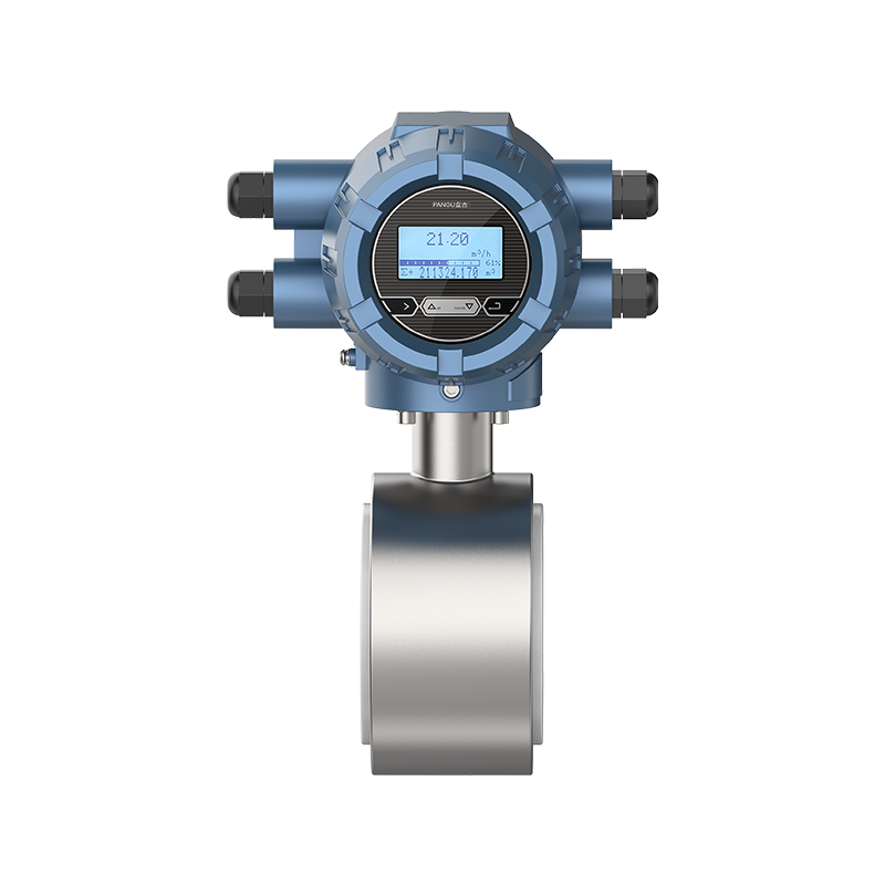
- Full-Pipe Conditions: If air bubbles are trapped or the pipe isn't 100% full during a short test burst, any standard flowmeter will read higher than the actual liquid mass collected on the scale. Because an integral electromagnetic flowmeter houses its sensor and transmitter in one unified housing, maintaining a full pipe is critical to avoid reading skews.
Fixing It On-Site: Adjusting the Span Factor and Zero Point
When our client encountered that 2% drift across their two integrated lines, they didn't need to ship the hardware back or fiddle with complex cabling. Instead, they performed a targeted field calibration directly on the meter's local display and keypad. Here is the general workflow they used:
Step 1 – Verify the Zero Point First
Ensure the line is completely filled with static fluid and zero flow is guaranteed. If the local display shows a tiny residual flow rate, adjust the electronic zero point immediately through the converter menu.
Step 2 – Check Installation and Environmental Conditions
Before changing the calibration factor, confirm:
- The pipe is fully filled with liquid.
- There are no significant air bubbles.
- Grounding is properly connected.
- The test flow is stable.
- There is no strong vibration or electrical interference nearby.
Step 3 – Calculate the Correction Coefficient
If the offset remains consistent and all external conditions are acceptable, the span factor can be recalculated:
New Factor = Old Factor × (Actual Weighed Mass / Meter Indicated Mass)
Or follow the manufacturer's calibration formula, as different brands may use K factor, sensor factor, span factor, or other naming conventions.
Step 4 – Input and Test
Update the span coefficient via the integral display interface, run a verification batch, and watch that 2% error drop down to within the agreed tolerance, such as ±0.5%, tolerance window.
Important Note: Changing the span factor will affect the factory calibration status. This adjustment should only be made by qualified instrument technicians, and the result should be documented for future reference. For trade settlement or legally controlled measurements, field coefficient changes should be verified by an authorized metrology provider.
Minimizing Field Adjustments with High-Precision Integral Hardware
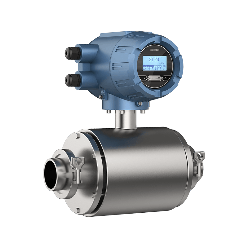
While field tuning is a great safety net, choosing robust, factory-calibrated instruments from a reliable Smart Electromagnetic Flow Meters Company cuts down commissioning headaches drastically.
If your processes demand tight tolerances right out of the box, partnering with professional Digital Electromagnetic Flow Meter Suppliers ensures each compact magnetic flowmeter undergoes rigorous multi-point wet calibration before shipping. For specialized installations, working directly with Custom Digital Electromagnetic Flow Meter Manufacturers allows you to tailor electrode materials and converter protocols to your exact media characteristics.
Furthermore, deploying a certified China High Accuracy Digital Electromagnetic Flow Meter drastically reduces baseline drift, ensuring that your instrument stays stable even under harsh industrial pressures without requiring frequent maintenance.
Specialized Scenarios: Beyond Standard Liquid Lines
Different applications require unique hardware configurations. Depending on your setup on-site, you might run into specific variants or deployment needs:
- Challenging Fluids: Measuring high-purity water, acids, or chemical slurries? A reliable Wholesale Low Conductivity Electromagnetic Flowmeter Factory can provide specialized low-noise electronics to keep signals clean. If you are sourcing in bulk, a trusted Wholesale Low Conductivity Electromagnetic Flowmeter Company ensures consistent batch quality.
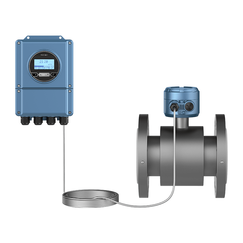
- Remote or Submerged Sites: When sensors are buried in wet vaults or hard-to-reach pits where an integral unit might be hard to access, a China Split Type Remote Electromagnetic Flow Meters Factory setup keeps the sensitive converter safely away from moisture.
Final Thoughts
A 2% calibration gap during a weighing test isn't a dead end—it's a standard part of fine-tuning industrial loops to match specific local conditions. By understanding how to adjust your span factors and choosing reliable integral instrumentation from the start, you can ensure long-term accuracy across every pipeline in your facility.
Want to know how to set up zero-point calibration and adjust span factors on an integral electromagnetic flow meter step by step?
Contact Us
Have questions about field calibration, selecting the right electromagnetic flow meter, or custom requirements for your application? Our engineering team is here to help.
Contact Us Now
PREV:Color TFT vs. Blue LCD vs. Monochrome: Which Paperless Recorder Fits Your Budget and Visibility Needs?
NEXT:How Can Hangzhou Pangu KT800 Optimize MLCC Manufacturing & Reliability Testing?
NEXT:How Can Hangzhou Pangu KT800 Optimize MLCC Manufacturing & Reliability Testing?
Interested in cooperation or have questions?
Contact Us Now!
Kelly

+86 13967196545

pangusales@vip.163.com
Production Base:

Building 1 and Building 42, No. 889 Huancheng North Road, Deqing County, Huzhou City, Zhejiang Province
Jiji
+86 15397010616
pgsalesjiji@vip.163.com

+86-0571-87770830
Corporate Headquarters:
602-702, Block D, Building 3, Area B,Xigang New Territories, 206 Zhenhua Road,Hangzhou City, Zhejiang Province, China

Copyright © Hangzhou Pangu Automation System Co., Ltd. Rights Reserved.
Custom Digital Panel Mount Industrial Instruments Suppliers
