 Read More

 Get A Quote

Engineering Guide to Electromagnetic Energy Meters in District Energy & HVAC Systems
Home / News / Industry News / Engineering Guide to Electromagnetic Energy Meters in District Energy & HVAC Systems
Product Category
NEW Category
Contact us
Contact Us
We specialise in the research, development and manufacture of electrical wires and cables.
 +86 13967196545
Related News
- Pangu Electromagnetic Flowmeters Cover Six Critical Industries, Enabling Process Control and Energy Savings
- Electromagnetic Flow Meter vs. Vortex Flow Meter: Principles, Differences, and Selection Guide
- Mastering Wastewater Flow: The Engineering, Selection, and Maintenance of Electromagnetic Flow Meters
- Overcoming Flow Measurement Bottlenecks in Water Treatment: A Selection & Application Guide for Hangzhou Pangu’s Three Core Electromagnetic Flowmeters
Engineering Guide to Electromagnetic Energy Meters in District Energy & HVAC Systems
Content
- 1 Technical Specification & Engineering Whitepaper
- 2 1. Introduction: Thermal Energy Sub-metering Challenges in Commercial Buildings
- 3 2. Technical Operating Principle & System Architecture
- 4 3. Key Selection & Engineering Considerations
- 5 4. Field Installation Guidelines & Fault-Tolerant Setup
- 6 5. Building Management System (BMS) Integration
- 7 6. Frequently Asked Questions (Technical FAQ)
1. Introduction: Thermal Energy Sub-metering Challenges in Commercial Buildings
In modern high-density commercial developments, district cooling networks, and centralized heating plants, accurate thermal energy sub-metering is the foundation of energy cost allocation, tenant billing, and operational optimization. Traditional mechanical energy meters rely on internal moving impellers. Over time, exposure to suspended solids, iron rust, and calcium scaling degrades mechanical accuracy, creates significant fluid pressure drops, and increases long-term maintenance costs.
To address these operational vulnerabilities, engineering teams are increasingly turning to full-bore electromagnetic energy meters (electromagnetic heat meters). Operating under Faraday’s Law of Electromagnetic Induction, these instruments measure fluid velocity without internal obstructions, delivering maintenance-free performance, high dynamic accuracy, and robust stability across chilled water and hot water loops.
2. Technical Operating Principle & System Architecture
An electromagnetic energy meter calculates thermal energy transfer by simultaneously measuring volumetric flow rate and temperature differential (ΔT) between supply and return lines. The thermal energy rate Q is computed using the following thermodynamic formula:
Q = ∫ qv · ρ(T) · Δh(Tsupply, Treturn) dt
Where qv represents volumetric flow rate derived via Faraday’s Law, ρ(T) is fluid density as a function of temperature, and Δh is the specific enthalpy differential calculated from precision temperature readings.
System Hardware Architecture
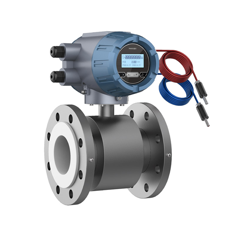
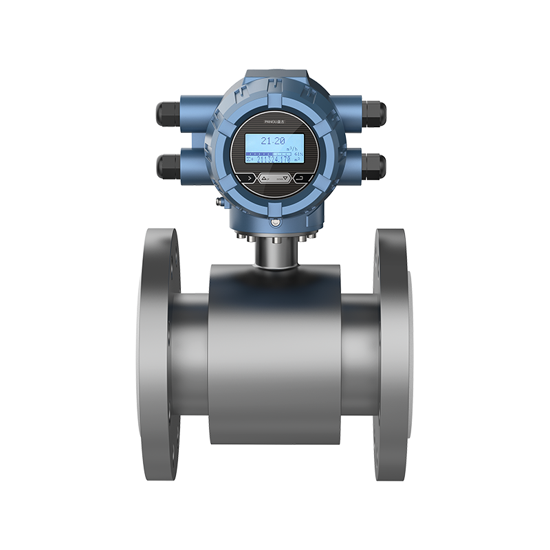
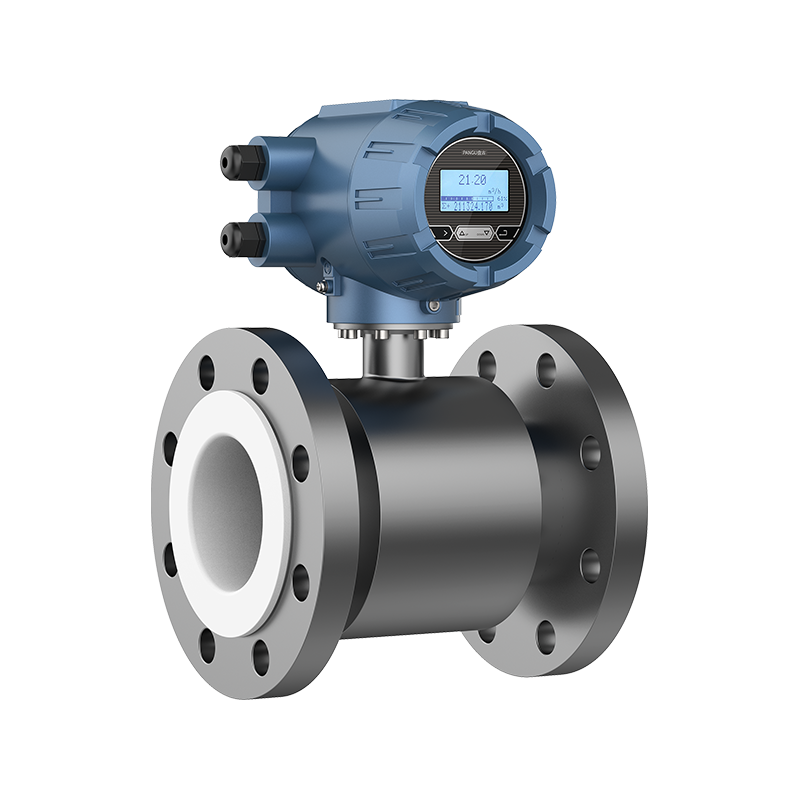
- Electromagnetic Flow Sensor: Full-bore flow tube equipped with non-corrosive linings (Neoprene or PTFE) and 316L stainless steel electrodes.
- Matched Pt1000 Temperature Sensors: Dual platinum resistance thermometers paired to within ±0.1°C accuracy to measure supply and return pipe temperatures.
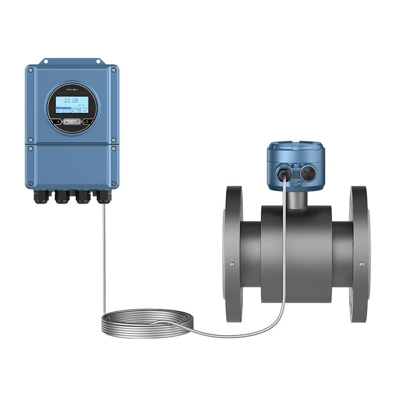
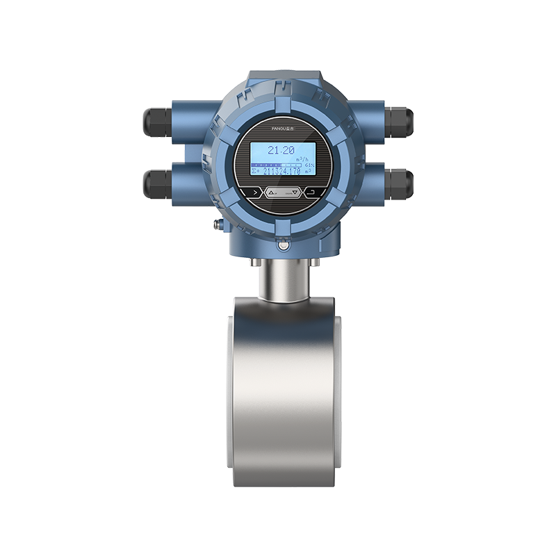
- Intelligent Energy Calculator (Converter): High-speed microprocessor calculating instant flow rate, temperature difference, accumulated cooling/heating energy (kWh, MWh, GJ), and diagnostics.
3. Key Selection & Engineering Considerations
3.1 Liner Material & Temperature Compatibility
Selecting the correct lining material is critical to preventing fluid erosion, chemical attack, and vacuum collapse:
- Neoprene Rubber (CR): Recommended for standard HVAC chilled water and low-temperature heating loops operating from 0°C to 80°C. Offers excellent wear, aging, and abrasion resistance.
- Polytetrafluoroethylene (PTFE): Essential for high-temperature water networks and industrial fluid loops operating from -25°C to 120°C. Provides complete chemical inertness and superior thermal endurance.
3.2 Flow Tube Diameter & Sizing Performance
Proper sizing prevents low-flow measurement dead zones while maintaining acceptable pressure thresholds. The table below details nominal pipe sizes (DN20 to DN300) along with corresponding flow boundaries from the Pangu PMH Series engineering specifications:
| Nominal Diameter (DN) | Flange Outer Dia. (mm) | Min Flow qi (m³/h) | Permanent Flow qp (m³/h) | Max Flow qs (m³/h) |
|---|---|---|---|---|
| DN20 | 105 | 0.05 | 2.5 | 5.0 |
| DN25 | 115 | 0.07 | 3.5 | 10.0 |
| DN40 | 150 | 0.20 | 10.0 | 25.0 |
| DN50 | 165 | 0.30 | 15.0 | 30.0 |
| DN80 | 200 | 0.80 | 40.0 | 80.0 |
| DN100 | 220 | 1.20 | 60.0 | 120.0 |
| DN150 | 285 | 3.00 | 150.0 | 300.0 |
| DN200 | 340 | 5.00 | 250.0 | 500.0 |
| DN300 | 445 | 12.00 | 600.0 | 1200.0 |
4. Field Installation Guidelines & Fault-Tolerant Setup
Improper piping configurations and grounding are the primary causes of field measurement errors. Adhere to the following engineering practices during installation:
4.1 Upstream & Downstream Piping Clearance
To ensure a fully developed symmetrical flow profile, install the flow sensor with at least 10D (10 × pipe diameter) of straight pipe upstream and 5D downstream. Control valves or throttling devices must always be located downstream of the sensor.
PIPING SCHEMATIC
Straight Run >= 10D PMH Sensor Straight Run >= 5D
======================> [ Electromagnetic Flow Tube ] ======================> [Valve]
Flow Direction Flow Direction
4.2 Grounding Requirements for Noise Immunity
Because electromagnetic meters measure microvolt-level induced signals, proper grounding is essential to eliminate electrical noise:
- Metal Pipes: Connect the sensor ground lug directly to adjacent pipe flanges using 2.5 mm² copper grounding wire (ground resistance < 10 Ω).
- Insulated or Plastic Pipes: Install stainless steel grounding rings between pipe flanges on both sides of the sensor to establish fluid contact.
- Stray Currents / Cathodic Protection: Ensure complete electrical isolation of the flow tube from stray current paths using insulated bolts and 16 mm² bonding conductors.
4.3 Smart Commissioning & Fault-Tolerant Feature
On complex construction sites, accidental reverse installation of supply/return pipes, temperature sensors, or flow direction can require costly re-plumbing. Pangu’s PMH Series features built-in software fault tolerance: physical direction errors can be corrected via simple touch-key menu settings or BMS commands without removing the meter from the line.
5. Building Management System (BMS) Integration
Modern smart buildings require seamless data telemetry. The PMH Series supports standard open protocols for direct integration into Siemens, Schneider, or Honeywell BMS platforms:
- Serial Communications: RS485 supporting Modbus-RTU and BACnet MS/TP.
- Analog & Pulse Outputs: 4-20mA current loop and frequency/pulse outputs for flow/heat rate transmission.
- Wireless Local Access: Bluetooth 4.0 interface for handheld field parameter configuration via a mobile application.
- Long-Distance Temperature Wiring: 4-wire Pt1000 connection architecture supports wire extensions up to 100 meters without resistance loss calibration issues.
6. Frequently Asked Questions (Technical FAQ)
Q1: What accuracy class does the PMH Electromagnetic Energy Meter satisfy?
The PMH Series complies with Class 2 accuracy under the GB/T 32224-2015 heat meter standard, featuring paired Pt1000 sensors with a temperature matching error within ±0.1°C.
Q2: How does an electromagnetic heat meter prevent pressure head loss?
Unlike mechanical heat meters with turbines or orifice plates, an electromagnetic meter features a full-bore, unobstructed flow tube design, resulting in zero additional pressure loss in HVAC circulation loops.
Q3: How are historical billing records preserved during power outages?
The converter contains non-volatile EEPROM memory that stores up to 18 months of monthly report data (accumulated cooling/heating consumption) even during complete mains power failures.
Interested in cooperation or have questions?
Contact Us Now!
Kelly

+86 13967196545

pangusales@vip.163.com
Production Base:

Building 1 and Building 42, No. 889 Huancheng North Road, Deqing County, Huzhou City, Zhejiang Province
Jiji
+86 15397010616
pgsalesjiji@vip.163.com

+86-0571-87770830
Corporate Headquarters:
602-702, Block D, Building 3, Area B,Xigang New Territories, 206 Zhenhua Road,Hangzhou City, Zhejiang Province, China

Copyright © Hangzhou Pangu Automation System Co., Ltd. Rights Reserved.
Custom Digital Panel Mount Industrial Instruments Suppliers
